The tracker is easy to build on a perfboard. I used a basic one-pad-per-hole perfboard and 26-gauge wire, but 30-gauge would probably be better. All the electronic parts are available from Mouser Electronics. Radio Shack sells the perfboard and the 2.5mm plug for the phone. You could also buy these from Mouser.
If you are building a tracker, please post in the user forum. I am looking for bug reports, pictures, and information about how the tracker works for you. I will provide technical support to people who are building units.
Click here for information about using the Aarlogic GPS 3A GPS module and Telit GC864 GSM module.
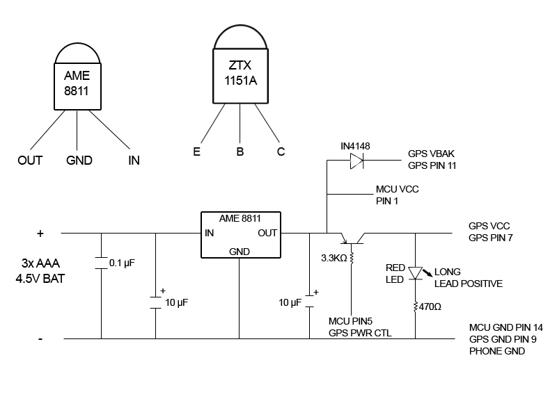
Caution: I have seen two units with the power transistor installed backward. If you reverse the emitter and collector, the transistor will conduct weakly. The power light comes on, but the device either returns NO DATASTREAM or never replies. With the regulator and transistor installed side by side, and the output of the regulator next to the emitter of the transistor, the flat sides of the two components face in opposite directions. If they are facing the same way, the circuit will not work!
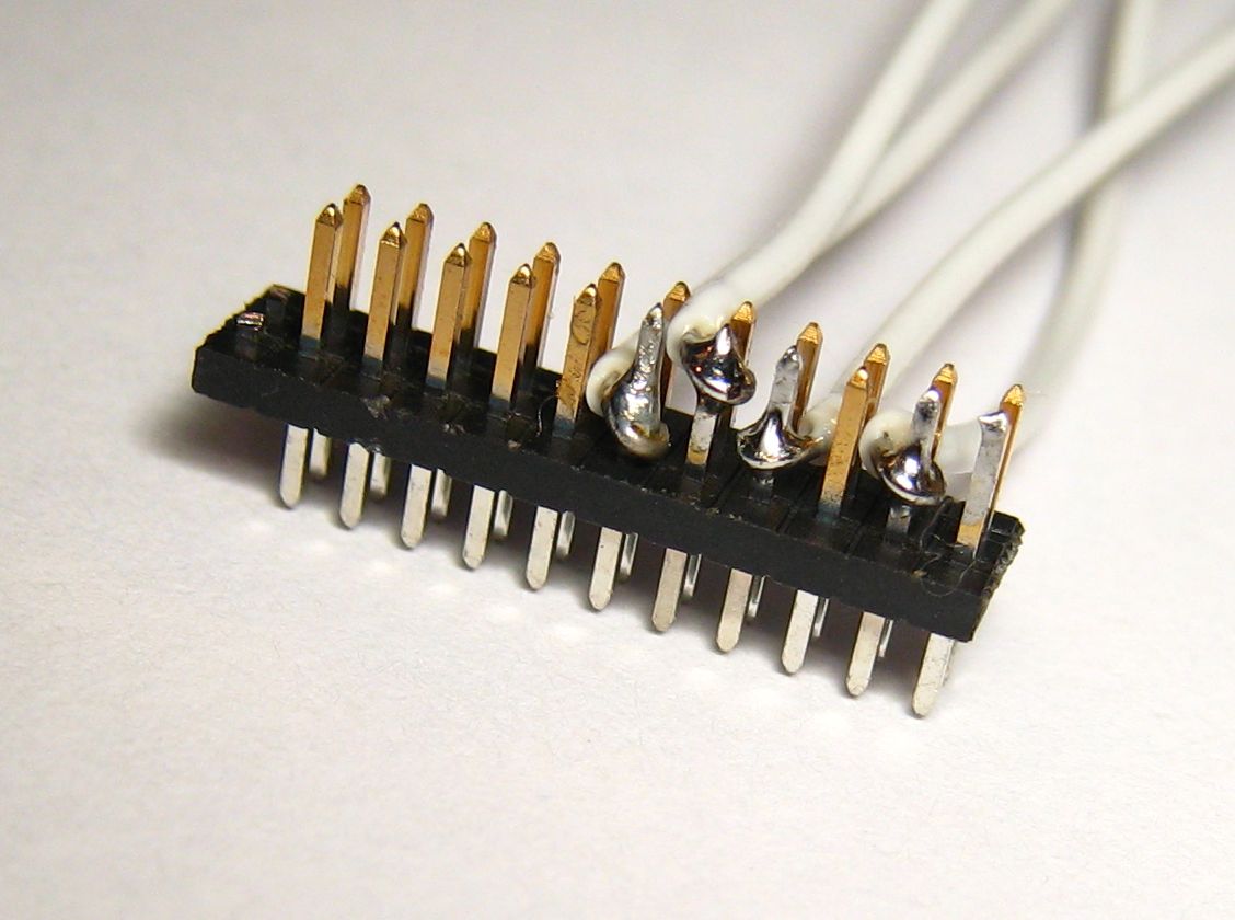
The Mouser Electronics (http://www.mouser.com) order is listed below. This order includes an AVRISP2, which you may not need if you already have an AVR programmer. I've included two each of all the small parts, and three of the GPS module connectors. This connector is the only tricky part of the build. It is easy to ruin one, as I did. For testing, you can just insert the 26-gauge wire into the socket on the GPS module, but for permanent assembly you need the connector. The connector has one extra pair of pins, which you should cut off. You will be soldering to the long side and plugging the short side into the GPS unit.
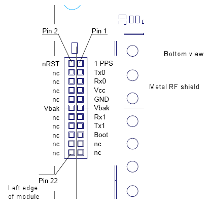
You need to solder to four pins on the GPS header, three of which are right next to each other. Clamp the header with a small vice or a "third hand" clip. Bend the wire into a loop with pliers and attach it to the pin, then carefully solder it. I solder pin 3 and pins 7 and 11 first, putting the wires down low near the plastic separator, then solder pin 9 with the wire up high away from pins 7 and 11. Check for shorts with a meter.
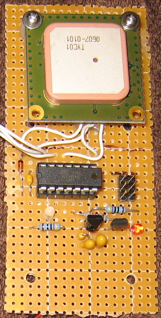
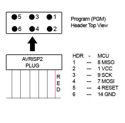
I superglued the IC socket and the two rows of three pins for the programming port, then wired those together and installed the rest of the components. Put the 0.1uF capacitor right next to the IC socket. The GPS module is attached to the board with 2-32 size screws, nuts, lock washers, and 1/4 inch spacers, which are not quite long enough. Get 3/8 inch spacers if you mount it this way.
| Mouser Part # | Description | Quantity | Price Each |
|---|---|---|---|
| 556-ATTINY84-20PU | Atmel AVR microcontroller | 2 | $2.90 |
| 827-AME8811AEATZ | 3.3 volt regulator | 2 | $0.69 |
| 522-ZTX1151A | PNP transistor with low saturation voltage | 2 | $1.51 |
| 581-SA105E104M | 0.1 uF ceramic capacitor | 10 | $0.08 |
| 581-TAP106K006SCS | 10 uF tantalum capacitor | 4 | $0.50 |
| 855-M50-3501242 | 1.27mm M50 connector for GPS device | 3 | $1.45 |
| 171-0025-EX | 2.5mm stereo plug for phone | 2 | $1.35 |
| 571-1-390261-3 or 571-26415994 | 14 pin IC socket | 2 | $0.15 |
| 604-WP937EGW | Two-color red/gren LED | 2 | $0.34 |
| 604-WP132XID | Red LED | 2 | $0.12 |
| 660MF1/4DC3321F | Resistor 3.32K ohm | 5 | $0.03 |
| 660MF1/4DC4700F | Resistor 470 ohm | 5 | $0.03 |
| 755-1N4148T-77 | Switching diode | 5 | $0.03 |
| 12BH431-GR | 3 AAA battery holder | 1 | $0.89 |
| 571-41032390 | Pin header 40-pin breakaway | 1 | $1.57 |
| 340-V23993-A1035D | Vincotech GPS receiver module | 1 | $61.50 |
| 556-ATAVRISP2 | AVRISP2 USB AVR programmer | 1 | $35.91 |
| Code | Description |
| 11 | phone polled |
| 12 | send message failed |
| 13 | phone poll failed |
| 14 | no phone number defined |
| 21 | invalid password |
| 31 | power on or reset |
| 32 | watchdog reset |
| 33 | eeprom initialized from defaults |
| 34 | remove jumper to reinit |
To set the reply address to a mobile phone number, use a mobile phone to send a
text message to the tracker's phone number:
GPS SETADDRESS 8185551212
where 8185551212 is the mobile number you want tracker messages sent to. The "GPS" must be uppercase.
The SETADDRESS can be upper or lower case. After sending the message, the tracker's phone
display should light, the tracker status light should blink code 11, and you should receive
a reply saying "COMMAND EXECUTED".
To set the reply address to an email account, you need your carrier's Email Gateway number,
which is a special phone number used to route text messages to an email account. For AT&T
the Email Gateway number is 121. For other carriers, go into the phone's SMS settings
(Messages, Options, Message Setup, Text Messages, Email Gateway) and look up the Email Gateway number. Send a text message to the tracker:
GPS SETADDRESS 121 user@domain.com
where "GPS" is in uppercase, 121 is the Email Gateway, and user@domain.com is the email
address. For AT&T service, you can send an email to phone-number@txt.att.net
(8185551212@txt.att.net) to send a text message. For other carriers, you will have
to look up the correct email address. The tracker will reply "COMMAND EXECUTED."
Requesting a locate
Once you have set your reply address, you can request a locate. Send the message:
GPS LOCATE
where GPS is in uppercase. The tracker's phone display will light, the status LED
should blink code 11, and the GPS power LED should come on. For the first locate, it
will usually stay on for a minute or more. When the GPS light goes out, the status
LED will blink code 11 again, and you should receive a reply:
LOCATE POS 34 05.8779 N 118 20.6368 W ALT 377 FT SPEED 0.0 MPH COURSE 11.05 AT 08/04/05 22:31:51 UTC SATS 04
This is a location report from the tracker. The fields are:
If you get "NO DATASTREAM FROM GPS DEVICE" your GPS module is not sending any data to the microcontroller. Check for faulty connections and verify that power is applied to the GPS module when the GPS power LED is lit. Dead GPS batteries can also cause this error, since the microcontroller needs less power than the GPS module.
Securing your tracker
The "GPS" prefix you have been putting before commands is actually a default password. You can and
should change it. Anyone who knows your password can change it and take control of the tracker.
Unlike commands, the password is case sensitive. To change it, send a text message like:
GPS SETPASSWORD newpass newpass
Where "newpass" is the new password you want to set. It must be between three and
sixteen characters, and must be repeated twice after SETPASSWORD. You should get back
"PASSWORD CHANGED." You would then have to send "newpass LOCATE" to request a locate, for example. If you lose your password, you need physical access to the tracker to clear the configuration (see the command reference.) Messages sent without the correct password will be ignored.
Other things the tracker can do
So far you have seen the normal mode, in which the tracker replies immediately to requests.
The tracker has two other modes: tracking and powersave.
In tracking mode, the tracker automatically takes GPS fixes, and sends you a message when it starts moving, when it stops moving, when it goes out of GPS coverage, and periodically while it is moving. You can plot the fixes on Google Maps or a similar service to follow the tracker's movements. You can configure how often the tracker takes a fix and how often it alerts you. You can also set a speed limit and receive an alert if it is exceeded.
In powersave mode, the tracker turns the phone power on and off periodically, allowing the phone battery to last longer than its typical standby time. For example, the phone may be off for an hour and on for ten minutes. In this case, it can take up to an hour for the tracker to reply to messages. You can remotely take the tracker out of powersave mode when you need location reports. Tracking and powersave modes are mutually exclusive; setting one mode clears the other.
The tracker has several configurable options, and a status command that reports the current settings, the phone battery status, the phone signal strength, and the firmware revision. You can set a name which will be prefixed to all tracker replies, so several trackers can report to the same destination. See the command reference for details.