 |
 |
|
|
I considered a speaking clock activated by a clap or whistle, but that would annoy anyone still sleeping, and would prevent me going back to sleep. The other obvious approach is a huge display or projection, but that would be awkward and generate too much light.
The Tracker's status LED provided the solution. This clock has a single two-color LED, and continuously blinks the time in hours and five-minute intervals. From reading analog clocks, we are all trained to multiply by five: if the big hand is on four, it's twenty minutes after the hour. Likewise, if the one-LED clock blinks red three times and then green four times, it is between 3:20 and 3:24.
RED-RED-RED-RED-PAUSE-RED-RED-RED-RED = 4:00 - 4:04
RED-RED-GREEN-GREEN-GREEN-GREEN-GREEN = 2:25 - 2:29
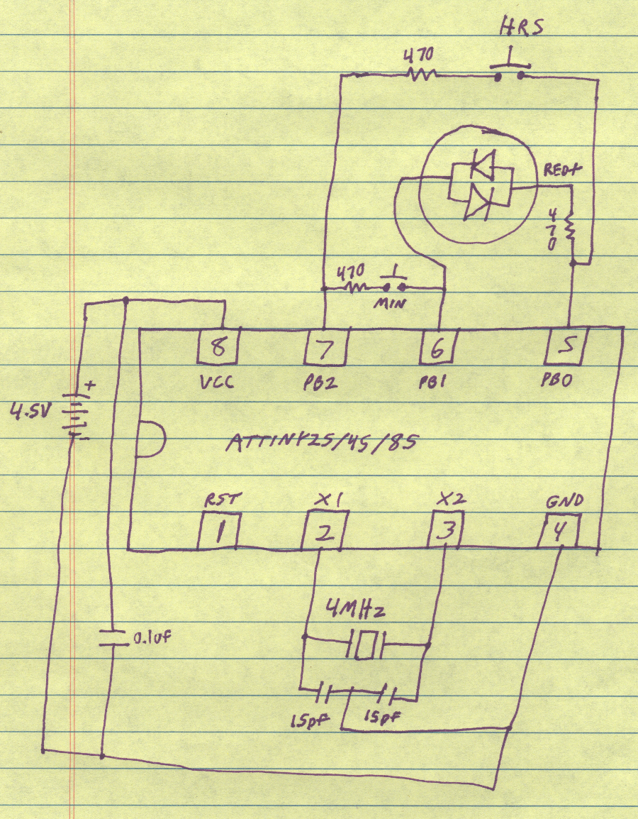
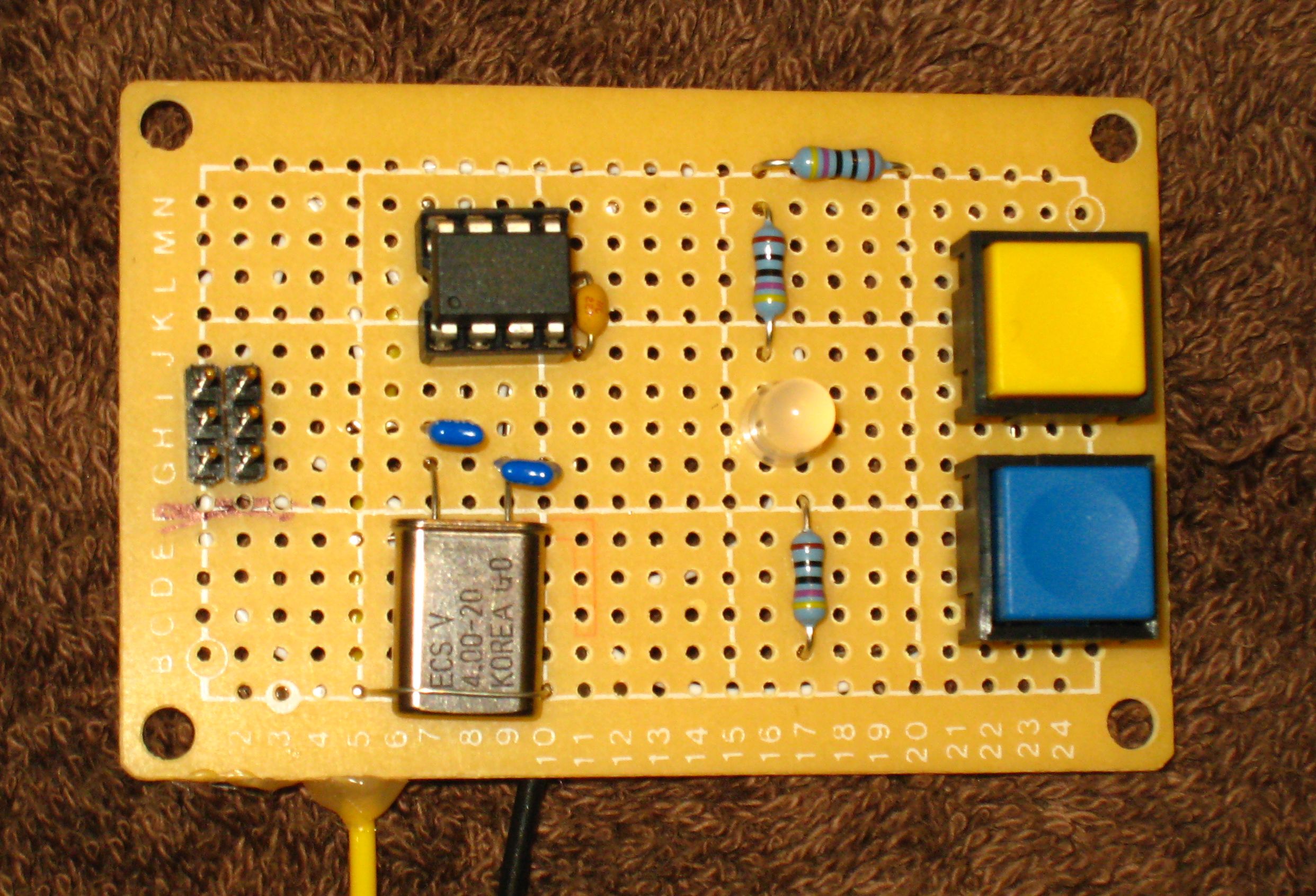
The clock uses a two-lead red/green LED, two buttons, a 4 MHz crystal, three capacitors, and three resistors. The board above has an ATTINY85, but you can use an ATTINY25 or ATTINY45, because the code is under 512 bytes. To assemble for the ATTINY25, comment out the SPH stack pointer setting line.
To set the clock, press the HOUR button to advance the hour one, and press the MINUTE button to advance the minute one. When you press either set button, the clock switches to a mode where it displays the exact minute in yellow. You will see the usual red-green sequence followed by zero to four yellow blinks indicating the minute. Three red, two green, three yellow means 3:13. After a couple of minutes the clock will revert to its normal output.
Since there is no display, there is no auto advance. The setting advances once per click. It starts up at 1:00, so press HOUR twice and MINUTE 20 times to set it to 3:20, and then check the output to make sure it is set right. Pressing MINUTE clears the seconds register, so you can set the clock accurate to the second. Pressing HOUR does not clear the seconds or minutes, so you can adjust for daylight savings time without resetting the minutes.
Pressing both keys simultaneously toggles minute-in-yellow mode. If enabled manually, it stays enabled until you turn it off or reset the time.
The clock requires 3-5 volts DC. With 4.0 volts, I measured 0.46 ma with the LED off and 4.70 ma with the LED on. Assuming the LED is on 40% of the time, the average current is 2.16 ma. Three 2.5ah alkaline AA cells should last 48 days, and three 14ah alkaline D cells shoud last 270 days. Current will decrease as the batteries wear out, so you might get longer life. Using a larger value LED resistor would increase battery life at the expense of a dimmer LED.
The CPU should be running at 500 KHz from a 4MHz crystal, using the divide-by-eight setting. To program your chip, set fuse bits CKSEL3:0 to 1101, SUT1:0 to 11, and set CKDIV8 programmed. The fuse bits show up as 0xFF, 0xDF, 0x7D on my programmer. If your clock runs much too fast (twice up to 16x) you have the fuse bits set wrong.
One LED clock V1.0 source code
One LED clock V1.0 hex image for the ATTINY85 and ATTINY45